


Network Model Alignment Part 2: What it is, why you need it, and how the CIM supports
In our first installment, we reviewed how network models are used in electric utilities and make a case for organizing key planning and operations around having a singular, rather than multiple, model representation of the network. So, how does the CIM support it? And what are some real-world applications (use cases)?
Model alignment for operations and planning means there is one power system network model that has all the necessary classes, attributes, and relationships needed for both operations models used in an EMS and planning models used by planning applications. In the CIM, there is a single unified network model that does exactly that. For the new network designs associated with network expansion, switches and breakers are not added at this stage of design, resulting in bus/branch network models.
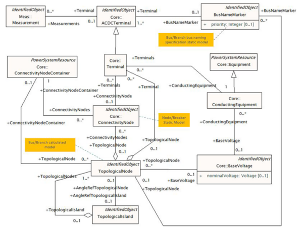
As shown in CIM Connectivity Model above (taken from the IEC CIM 61970-301), there are key components namely:
- Terminal
- ConnectivityNode
- ConductingEquipment
- TopologicalNode
- ToplogicalIsland
- EquipmentContainers
- ConnecvityNodeContainer
- BusNameMarker
So how does this work? The IEC CIM 61970-301 documents the interconnection logic of the model:
“Terminal and ConnectivityNode classes are defined to represent a model connectivity in the CIM, A Terminal belongs to one ConductingEquipment, although ConductingEquipment may have any number of Terminals. Each Terminal may be connected to a ConnectivityNode, which is a point where terminals of conducting equipment are connected with zero impedance. A ConnectivityNode may have any number of terminals connected and may be a member of a TopologicalNode (i.e. a bus), which is in turn a member of a TopologicalIsland. TopologicalNode-s and TopologicalIsland-s are created as a result of a topology processor evaluating the “as built” connectivity and the actual Switch positions at some point in time.
It is possible to exchange documents directly involving TopologicalNode and bypassing the ConnectivityNode details by using the TopologicalNode to Terminal association. This is used for exchanges involving bus/branch models which do not contain switch detail. When the TopologicalNode model is exchanged, it is useful to also exchange the “connected” attribute on the Terminal class. This allows for the topological structure of the model to be retained, yet indicate a terminal is not completely connected. Normally, this disconnection is the result of one or more switches opening in the detailed model which is not represented in a model exchange without switch detail.
EquipmentContainers, which are a specialization of a ConnectivityNodeContainer, may contain zero or more ConnectivityNodes. The associations, ConductingEquipment–Terminal and Terminal–ConnectivityNode, capture the as-built connectivity of an actual power system network. For each Terminal connected to a ConnectivityNode, the associations of the other Terminal(s) connected to the same ConnectivityNode identify the ConductingEquipment object(s) that are electrically connected.
Similar connectivity at the bus/branch level of detail can be expressed using the TopologicalNode instead of the ConnectivityNode. The BusNameMarker class, which has an association to ConnectivityNode, is used to carry user bus names to be applied to TopologicalNodes. A TopologicalNode is created from multiple ConnectivityNodes as a result of topology processing, and various names might be applied depending upon which ConnectivityNode instances are present.”
Use Cases
When we first tackled “harmonization” of the CIM and 61850 were harmonized years ago on an EPRI project, we realized this problem was intractable unless we identified a few use cases so that we could restrict the scope of the effort. Compared to that effort, this alignment of two different representations of a network, both in the CIM model, can be straight forward with a good strategy/plan of attack and truly understanding the size of the problem and the utility’s capabilities to tackle it.
Use Case 1: Export as-built node/breaker model from an EMS for planning to conduct a case study
This use case would be used as a foundational building block to add one or more network extension projects, thus creating one or more complete models to do power flow studies or other types of case studies
For planning to use it, the as-built model must first be converted to a bus/branch model in the NMS to remove all the switches and breakers and rename the topology nodes with using the previously saved BusNameMarker instances to name the buses. The NMS then would export the newly re-instantiated bus/branch model which would contain all the changes to the EMS model since planning last saw it.
If the Substation in question has been automated using the 61850 standards, so that there is a 61850-based SS model, then there may be some additional tools available, as well as supporting use cases. For example, if all the equipment including switches and breakers was automated and defined using 61850, then there is the possibility of importing a Substation Control Language (SCL) file as defined in 61850 and converting that to a CIM-based EMS node/breaker model. But this may be unduly complicating things at this stage.
Use Case 2: Export a network extension project’s bus/branch model for substation for use in an EMS
For operations to use it, the bus/branch model must first be converted to a node/breaker model. Ideally, diving a little deeper, planning would first submit their bus/branch model to a Network Model Management System (NMM) where Engineering would add the switches and breakers, thus creating a node/breaker model. Then the NMM would export the node/breaker to the EMS in operations where it would be added as a network extension to the existing EMS Model.
Conclusion
Aligning planning may appear to be a daunting and overwhelming task in a utility where the quantity of busses Engineering needs to elaborate numbers in the thousands. Xtensible recommends as a preliminary step to embarking on the alignment journey that utilities conduct an assessment to ‘measure the size of the problem’, assess its current capabilities, align people, processes and technology and identify any opportunities for streamlining the process via data profiling and automation which could potentially save hundreds of hours of effort.
Xtensible wants to make sure that our customers are aware and best equipped as possible to take on planning and operations model alignment. The key takeaways here is identifying use cases, preferably using the template developed by WG13 and WG14, to get a better handle on the problem(s) you are solving and then assess the organizational capabilities (people, processes, technology and data) ability to realize them.
To learn more about who is using the CIM check our recent blog post of Are Utilities in the U.S. Utilizing the IEC CIM, this can give you some insights into who is taking this approach.
Back To Blog
